
2.3 - Working with Vertex Attributes
What We're Learning
In our journey so far, we've treated vertices as simple points in space, focusing exclusively on how to transform their POSITION from local coordinates to the screen. But a vertex is much more than a point; it's a rich packet of information that describes the properties of a mesh's surface at that specific location. Beyond position, vertices carry data like normals for lighting, UV coordinates for texturing, and even custom colors.
Vertex attributes are the bridge between your CPU-side mesh data (in Rust) and your GPU-side shader program (in WGSL). They are the mechanism by which you send this detailed, per-vertex information across the pipeline. Mastering them is the key to unlocking materials that are not uniform, but instead have rich, varied surfaces that respond to light, display complex textures, and feature intricate, procedurally generated patterns.
By the end of this article, you'll have a firm grasp of this fundamental concept. You will learn:
The purpose of standard vertex attributes:
POSITION,NORMAL,UV_0, andCOLOR.How to read and use normals for foundational lighting calculations.
The role of UV coordinates in creating procedural, surface-aligned patterns.
How to use per-vertex colors for efficient, texture-free gradients.
The critical concept of interpolation and how data flows from the vertex shader to the fragment shader.
How to control interpolation with the
@interpolateattribute for effects like flat shading.The complete workflow for creating and using custom vertex attributes, including the crucial
specializemethod.How to visualize abstract vertex data (like normals or UVs) as color for debugging and artistic effects.
Understanding Vertex Attributes
Every vertex in a 3D mesh is more than just a point in space; it's a data packet containing all the information needed to describe the surface at that exact location. When you load a .gltf file or create a Mesh in Bevy, you are defining lists of these attributes. Bevy then efficiently streams this data to the GPU, where the vertex shader's first job is to receive and interpret it.
The Standard Attribute Set
While you can create any custom attributes you like, Bevy defines a standard set for the most common rendering tasks. When you create or load a mesh, it will typically have some combination of these:
POSITION: Avec3<f32>representing the location of the vertex in its local (model) space. This is the only truly required attribute.NORMAL: Avec3<f32>vector indicating the direction the surface is facing. This is essential for all lighting calculations.UV_0: Avec2<f32>representing 2D texture coordinates. It's the "address" of a pixel on a texture image, used to wrap the image around the model. (The_0implies you can have more, likeUV_1, for advanced techniques).COLOR: Avec4<f32>that assigns a specific color to the vertex. This allows for creating smooth color gradients across a surface without needing a texture.TANGENT: Avec4<f32>used for more advanced lighting techniques like normal mapping, which we'll cover in a later phase.
In your Rust code, you would provide a separate list of data for each attribute you want your mesh to have.
The Vertex Input Struct in WGSL
In your WGSL shader, you define an input struct for your @vertex entry point to receive this stream of data. The @location(N) decorator is the critical link. It's a contract that tells the GPU which piece of the incoming vertex data to map to which struct field.
Think of it like a set of numbered mailboxes. When Bevy sends a vertex to the GPU, it puts the POSITION data in mailbox 0, the NORMAL data in mailbox 1, and so on. Your shader's VertexInput struct must then go to the correct mailbox to retrieve the data it needs.
// This WGSL struct is the "receiver" for the data sent from Bevy.
struct VertexInput {
    // @builtin(instance_index) is provided by the GPU, not the mesh.
    @builtin(instance_index) instance_index: u32,

    // The @location(N) numbers are the key. They MUST match Bevy's layout.
    @location(0) position: vec3<f32>, // Receives ATTRIBUTE_POSITION
    @location(1) normal: vec3<f32>,   // Receives ATTRIBUTE_NORMAL
    @location(2) uv: vec2<f32>,       // Receives ATTRIBUTE_UV_0
    @location(3) color: vec4<f32>,    // Receives ATTRIBUTE_COLOR
}

@vertex
fn vertex(in: VertexInput) -> VertexOutput {
    // You can now access the attributes for the current vertex via the 'in' parameter.
    let local_position = in.position;
    let vertex_normal = in.normal;
    let texture_coords = in.uv;
    let vertex_color = in.color;

    // ... continue to transform and use them ...
}
This mapping is non-negotiable and a common source of bugs. For a standard Bevy Mesh, the data is laid out in a specific order, and your shader must respect it. If you declare @location(1) as a vec2<f32> but the mesh provides a three-component NORMAL vector at that location, the data types will not align. This can cause your shader to fail compilation or, in more subtle cases, to run but produce visual garbage as it misinterprets the raw data.
The standard layout is:
| Location | Bevy Attribute | WGSL Type |
| 0 | Mesh::ATTRIBUTE_POSITION | vec3<f32> |
| 1 | Mesh::ATTRIBUTE_NORMAL | vec3<f32> |
| 2 | Mesh::ATTRIBUTE_UV_0 | vec2<f32> |
| 3 | Mesh::ATTRIBUTE_COLOR | vec4<f32> |
If a mesh doesn't have a particular attribute (for example, vertex colors), you simply omit that field from your VertexInput struct. As we'll see later, custom attributes should always start at a location number after the standard ones your mesh uses to avoid conflicts.
Working with Normals
Normals are vectors that define the orientation of a surface at a specific point. The term "normal" is a synonym for "perpendicular" in geometry. For any given triangle in your mesh, a normal is a vector that points straight out from its surface. They are the single most important piece of data for creating believable lighting.
What Normals Represent
Imagine a flat tabletop. The normal vector at any point on that table would point straight up towards the ceiling. If you tilt the table, the normal vector tilts with it, always staying perpendicular to the surface.

Each vertex in a mesh stores a normal, and how these normals are calculated determines how the surface is shaded:
Flat Shading: For a mesh with sharp, flat faces (like a cube), the normals of all vertices on a given face will point in the exact same direction. This creates a faceted, low-poly look where each face has a uniform brightness.
Smooth Shading: For a mesh with a smooth, curved surface (like a sphere), the normal at each vertex is an average of the normals of the surrounding faces. This allows light to transition smoothly across the surface, creating the illusion of a continuous curve. This is the default for most 3D models.
Reading and Transforming Normals
Just like vertex positions, normals are initially defined in local (model) space and must be transformed into world space for lighting calculations to be consistent. However, a critical pitfall awaits: you cannot transform a normal vector with the same model matrix you use for position.
Why? Because normals represent direction, not location. Imagine a sphere that you scale to be half as tall (a non-uniform scale). The vertex positions are correctly squashed. But if you apply that same squash operation to the normals on the side of the sphere, they will be incorrectly tilted inwards instead of pointing straight out from the new, flattened surface. The correct transformation requires a special matrix, often called the "normal matrix," which is the transpose of the inverse of the model matrix.
Thankfully, you don't need to calculate this yourself. Bevy's standard shader imports provide a dedicated helper function that handles this complexity for you.
// In the vertex shader...
#import bevy_pbr::mesh_functions
#import bevy_pbr::view_transformations::position_world_to_clip

// ...

@vertex
fn vertex(
    @builtin(instance_index) instance_index: u32,
    @location(0) position: vec3<f32>,
    @location(1) normal: vec3<f32>,
) -> VertexOutput {
    var out: VertexOutput;

    // First, transform the vertex position to world space as before.
    let model = mesh_functions::get_world_from_local(instance_index);
    let world_position = mesh_functions::mesh_position_local_to_world(
        model,
        vec4<f32>(position, 1.0)
    );

    // Now, transform the normal to world space using Bevy's dedicated helper.
    // This function correctly handles non-uniform scaling behind the scenes.
    let world_normal = mesh_functions::mesh_normal_local_to_world(
        normal,
        instance_index
    );

    // Pass the transformed normal to the fragment shader.
    out.world_normal = world_normal;
    out.position = position_world_to_clip(world_position.xyz);
    out.world_position = world_position.xyz; // Also pass world position
    return out;
}
Key Principles for Handling Normals
Use the Right Function: Always use
mesh_functions::mesh_normal_local_to_worldto transform normals. Do not multiply them by the standard model matrix.Always Normalize: Transformations and, as we'll see soon, interpolation can introduce tiny floating-point errors that cause a vector to no longer have a perfect length of 1.0. The math for lighting relies on normals being "unit vectors" (length of 1.0). You must
normalize()them in the fragment shader before any lighting calculation to guarantee correct results.
Using Normals for Lighting
Once the world_normal arrives in the fragment shader (smoothly interpolated across the triangle's surface), we can use it to calculate lighting. The simplest lighting model is called Lambertian diffuse lighting. This model describes how light reflects equally in all directions from a matte surface, like chalk or unfinished wood.
The brightness of the surface depends entirely on the angle between its normal and the direction to the light source. The dot() product is the perfect mathematical tool for this, as it tells us how much two vectors are pointing in the same direction.
// In the fragment shader...
@fragment
fn fragment(in: VertexOutput) -> @location(0) vec4<f32> {
    // 1. Get a reliable, unit-length normal vector for this specific pixel.
    // This is the most important step for correct lighting.
    let normal = normalize(in.world_normal);

    // 2. Define a fixed direction for a light source (e.g., up and to the right).
    let light_dir = normalize(vec3<f32>(1.0, 1.0, 1.0));

    // 3. Calculate the dot product between the normal and the light direction.
    // - The result is 1.0 if they are parallel (light hits head-on).
    // - The result is 0.0 if they are perpendicular (light glances off the edge).
    // - The result is negative if they point in opposite directions (surface is in shadow).
    // We use max(..., 0.0) to clamp the result, ensuring surfaces facing
    // away from the light are just black, not "negatively" lit.
    let diffuse_intensity = max(0.0, dot(normal, light_dir));

    // 4. Add a little ambient light so the dark side isn't pure black.
    let ambient_light = 0.2;
    let lighting_factor = ambient_light + diffuse_intensity * 0.8;

    // 5. Apply the calculated lighting to a base color by multiplication.
    let base_color = vec3<f32>(0.8, 0.3, 0.3); // A simple red
    return vec4<f32>(base_color * lighting_factor, 1.0);
}
This simple model is the foundation of almost all real-time 3D lighting. By comparing the surface normal to the light direction, we can determine how much light a pixel should receive, bringing our 3D objects to life.
UV Coordinates: Mapping 2D to 3D
While normals are essential for lighting, UV coordinates are the foundation of texturing. They solve the fundamental problem of how to wrap a flat, 2D image (like a JPEG or PNG) onto the surface of a complex 3D model. The name "UV" is used simply to distinguish these 2D coordinates from the 3D XYZ coordinates of the vertex position.
Understanding UV Space
Think of UV coordinates as a set of instructions. Each vertex in a 3D mesh is assigned a 2D coordinate that corresponds to a specific point on a 2D texture. This process, called "UV unwrapping," is typically done in 3D modeling software like Blender, where an artist effectively flattens the 3D model's surface into a 2D pattern.
The UV coordinate system is normalized, meaning it's a square where both the U (horizontal) and V (vertical) axes range from 0.0 to 1.0, regardless of the texture's pixel dimensions.

By assigning a UV coordinate to each vertex of a triangle, you are "pinning" that part of the 3D model to a corresponding point on the 2D texture. The GPU then automatically stretches and fits the texture image across the triangle's surface based on these pins.
Basic UV Usage
For the most part, the vertex shader's job is simply to receive the UV coordinates from the mesh and pass them directly through to the fragment shader. They are 2D data and don't require the 3D transformations that positions and normals do. The real work happens in the fragment shader, where the interpolated UVs are used to sample (read the color from) a texture.
Even without a texture, we can use the interpolated UV values to generate procedural patterns, which is a powerful way to create interesting surfaces without relying on image files.
// Input struct must include the uv attribute.
struct VertexInput {
    // ...
    @location(2) uv: vec2<f32>, // Receives Mesh::ATTRIBUTE_UV_0
}

// Output struct must have a field to pass the UVs along.
struct VertexOutput {
    // ...
    @location(2) uv: vec2<f32>, // Pass the UVs to the fragment stage
}

@vertex
fn vertex(in: VertexInput) -> VertexOutput {
    var out: VertexOutput;
    // ... transform position and normal ...

    // UVs are usually just passed through directly.
    out.uv = in.uv;

    return out;
}

@fragment
fn fragment(in: VertexOutput) -> @location(0) vec4<f32> {
    // The `in.uv` value received here has been smoothly interpolated
    // for every single pixel across the triangle's surface.

    // Let's create a procedural checkerboard pattern.
    // `* 8.0` makes the pattern repeat 8 times across the surface.
    let scaled_uv = in.uv * 8.0;

    // `fract()` gives the fractional part, creating a repeating 0-1 gradient.
    let sawtooth_wave = fract(scaled_uv);

    // `step(0.5, ...)` converts the gradient into a square wave (0 or 1).
    let square_wave = step(vec2(0.5), sawtooth_wave);

    // Combine the x and y components to create the 2D checkerboard.
    // XORing the components (a * (1-b) + (1-a) * b) does the trick.
    let checker = square_wave.x * (1.0 - square_wave.y) + (1.0 - square_wave.x) * square_wave.y;

    return vec4(vec3(checker), 1.0);
}
UV Manipulation Techniques
The real power of UVs in shaders comes from manipulating them before you sample a texture or generate a pattern. This allows for a huge range of dynamic and procedural effects.
Tiling
Multiply the UVs by a scalar to make the texture or pattern repeat.
// The texture will now appear tiled 4 times in each direction.
let tiled_uv = in.uv * 4.0;
Scrolling
Add a time-varying offset to the UVs to create movement, perfect for flowing water, conveyor belts, or animated backgrounds.
// Scrolls the texture horizontally over time.
let scrolled_uv = in.uv + vec2<f32>(time * 0.1, 0.0);
Distortion
Add a procedural offset (like a sine wave or noise) to warp the UVs, creating effects like heat haze or underwater ripples.
let distortion_strength = 0.05;
let distortion = sin(in.uv.y * 20.0 + time) * distortion_strength;
let distorted_uv = in.uv + vec2<f32>(distortion, 0.0);
Radial Mapping
Convert the Cartesian (u, v) coordinates into polar coordinates (angle, radius) to create circular patterns, radars, or ripples emanating from a central point.
let center = vec2<f32>(0.5); // Center of the UV space
let to_center = in.uv - center;
let angle = atan2(to_center.y, to_center.x); // Angle from the center, in radians
let radius = length(to_center); // Distance from the center
let center = vec2<f32>(0.5); // Center of the UV space
let to_center = in.uv - center;
let angle = atan2(to_center.y, to_center.x); // Angle from the center, in radians
let radius = length(to_center); // Distance from the center
Vertex Colors: Artistic Freedom
Vertex colors provide a powerful and efficient way to add color detail to a mesh without using any textures. Instead of sampling a color from an image, you store the color data directly in each vertex of the mesh itself. The GPU then automatically blends these colors across the face of each triangle, creating smooth and often beautiful gradients.
Why Use Vertex Colors?
While textures are great for photorealistic detail, vertex colors excel in several key areas:
Performance: Reading from a vertex attribute is significantly faster than performing a texture lookup in the fragment shader. For simple gradients or stylized art, this is a major performance win.
Artistic Control: They are perfect for stylized aesthetics, soft gradients (like a sunset sky), or baking lighting information like ambient occlusion directly into a model. Game artists often use vertex painting tools in Blender to "paint" colors onto a model's corners, adding unique detail and variation.
Data Channel: The
vec4<f32>color attribute doesn't have to be used for color! It can be a convenient channel to pass any four floating-point values per vertex, such as animation weights, wind strength, or material properties that can be interpreted by the shader.
Reading Vertex Colors
Accessing vertex colors is identical to accessing normals or UVs. You add a field to your VertexInput struct at @location(3) and create a corresponding output field to pass the data through to the fragment shader.
// Add the color attribute to the input struct.
struct VertexInput {
    // ...
    @location(3) color: vec4<f32>, // Receives Mesh::ATTRIBUTE_COLOR
}

// Add a field to the output struct to pass it along.
struct VertexOutput {
    // ...
    @location(3) vertex_color: vec4<f32>, // Pass interpolated color to fragment
}

@vertex
fn vertex(in: VertexInput) -> VertexOutput {
    var out: VertexOutput;
    // ... transformations for position and normal ...

    // Pass the vertex color directly to the fragment shader.
    // The GPU will handle the interpolation automatically.
    out.vertex_color = in.color;

    return out;
}

@fragment
fn fragment(in: VertexOutput) -> @location(0) vec4<f32> {
    // 'in.vertex_color' is the smoothly blended color for this specific pixel.
    // If the triangle's vertices were red, green, and blue, this value might be
    // orange, purple, or cyan depending on the pixel's location.
    return in.vertex_color;
}
Combining Vertex Colors with Other Data
The real power comes from using vertex colors as the base color for other calculations, like lighting. Instead of using a hard-coded color in the fragment shader, you use the interpolated vertex color. This is called modulation: you modulate (multiply) the vertex color with the lighting value.
@fragment
fn fragment(in: VertexOutput) -> @location(0) vec4<f32> {
    // 1. Calculate lighting factor as before.
    let normal = normalize(in.world_normal);
    let light_dir = normalize(vec3<f32>(1.0, 1.0, 1.0));
    let diffuse = max(0.0, dot(normal, light_dir));
    let lighting_factor = 0.3 + diffuse * 0.7; // ambient + diffuse

    // 2. Modulate the interpolated vertex color by the lighting factor.
    // We multiply the RGB components, leaving alpha untouched.
    let lit_color = in.vertex_color.rgb * lighting_factor;

    return vec4<f32>(lit_color, in.vertex_color.a);
}
This simple multiplication correctly applies the calculated lighting to the smoothly blended base color from the mesh. A brightly lit area will show the vertex color at full intensity, while a shadowed area will show a darker shade of that same interpolated color, creating a cohesive and beautifully shaded result.
Controlling Data Flow: The Interpolation Stage
We've seen how to read attributes like normals, UVs, and colors in the vertex shader. But how do those values, defined only at the corners of a triangle, become the smooth, continuous surfaces we see in the fragment shader?
The answer, as we first introduced in article 1.6, is interpolation. After the vertex shader runs for all three vertices of a triangle, the GPU's rasterizer hardware takes over. For every pixel covered by that triangle, it automatically generates a blended value for each output of your vertex shader.
In this article, we're not just passing position; we're passing normals, UVs, and colors. The interpolation mode has a dramatic and direct effect on how this attribute data is perceived by the user. WGSL gives us the @interpolate attribute to control this process.
perspective: The Default for 3D Surfaces
By default, all outputs are interpolated with perspective correction. This is the highest-quality mode and is essential for any data that "sticks" to the 3D surface.
For UVs: Without perspective correction, textures on a surface receding into the distance would appear to warp and "swim" incorrectly. This mode is non-negotiable for correct texture mapping.
For Normals & Colors: It ensures that lighting and color gradients appear stable and are calculated correctly in 3D space.
For 99% of the attributes you pass from a 3D model, you will want the default perspective-correct behavior.
flat: Disabling Interpolation for a Purpose
There are times when you want to prevent blending entirely. @interpolate(flat) instructs the GPU that every pixel within a triangle should receive the exact, unmodified value from a single "provoking vertex" (usually the first vertex of the triangle).
The most common use case is to take a mesh with smooth vertex normals and render it with flat shading for a faceted, low-poly aesthetic. You are telling the GPU: "Take the normal from the first vertex of this triangle and use that same normal for the entire face."
// In your VertexOutput struct
struct VertexOutput {
    // ...
    @location(0) @interpolate(flat) flat_normal: vec3<f32>,
}

@vertex
fn vertex(in: VertexInput) -> VertexOutput {
    var out: VertexOutput;
    // ... calculate world_normal ...

    // We send the vertex's normal to this output.
    // The @interpolate(flat) attribute ensures it won't be blended.
    out.flat_normal = world_normal;
    return out;
}

@fragment
fn fragment(in: VertexOutput) -> @location(0) vec4<f32> {
    // The value of in.flat_normal is identical for every pixel of this triangle.
    // We can use it directly for lighting to get a faceted look.
    let diffuse = max(0.0, dot(in.flat_normal, light_dir));
    // ...
}
This is also essential for passing discrete data that must not be blended, like a material type ID (u32). You cannot average ID=2 and ID=5 to get a meaningful result.
linear: The Niche Case for Screen-Space Effects
@interpolate(linear) performs a simple 2D blend across the screen. It's faster but incorrect for 3D surfaces. Its primary use is for effects that are detached from the 3D geometry and operate purely in screen space, like a UI vignette where you want to darken the corners of the viewport. We will revisit this in the post-processing phase.
Creating Custom Vertex Attributes
While Bevy's standard attributes cover the most common rendering needs, you are not limited to them. You can define and send almost any per-vertex data you can imagine from your Rust code to your shader. This unlocks a vast range of possibilities for unique visuals and gameplay mechanics that are directly tied to your mesh data.
For example, you could store:
Wind strength or sway phase to animate foliage.
Bone indices and weights for skeletal animation.
A "wetness" or "temperature" value to visualize environmental interactions.
Surface type information (e.g., grass, rock, sand) for texture blending on terrain.
The process involves three key steps: defining the attribute in Rust, adding the data to a Mesh, and, most importantly, telling your material's render pipeline how to read it.
1. Defining a Custom Attribute in Rust
First, you must declare your custom attribute as a static MeshVertexAttribute. This object serves as a unique identifier, containing a debug name, a unique ID, and the data format.
use bevy::render::mesh::MeshVertexAttribute;
use bevy::render::render_resource::VertexFormat;

// Define a custom attribute for a single float value per vertex.
// The ID (a u64) must be unique.
pub const ATTRIBUTE_BLEND_WEIGHT: MeshVertexAttribute =
    MeshVertexAttribute::new("BlendWeight", 988540917, VertexFormat::Float32);

// Define another for a 4-component integer vector per vertex.
pub const ATTRIBUTE_BONE_INDICES: MeshVertexAttribute =
    MeshVertexAttribute::new("BoneIndices", 988540918, VertexFormat::Uint32x4);
Name: A string used for debugging and diagnostics.
ID: A
u64that must be unique across your entire application. If two different attributes use the same ID, Bevy's renderer will get confused. A good practice is to generate a randomu64or use a hash of the attribute's name to ensure it doesn't collide with attributes from other plugins or parts of the engine.Format: The VertexFormat enum specifies the data type and size. This must match the type you use in your WGSL shader.
The VertexFormat enum is a descriptor, not a Rust type itself. It tells Bevy what kind of data to expect. Here is how the formats map between your Rust code and your WGSL shader:
| VertexFormat | Data Type in Rust (vec![...]) | Data Type in WGSL (@location(N)) |
Float32 | f32 | f32 |
Float32x4 | [f32; 4] | vec4<f32> |
Uint32x4 | [u32; 4] | vec4<u32> |
Sint32x4 | [i32; 4] | vec4<i32> |
2. Adding Custom Attributes to a Mesh
Once defined, you add data to a mesh using insert_attribute, just as you would for standard attributes. The key is to use your newly defined constant as the attribute identifier. The Vec of data you provide must contain one entry for every vertex in the mesh.
// The length of this Vec must match the number of vertices in the mesh.
mesh.insert_attribute(
    ATTRIBUTE_BLEND_WEIGHT,
    vec![0.0_f32, 0.5, 1.0], // One f32 for each vertex
);

mesh.insert_attribute(
    ATTRIBUTE_BONE_INDICES,
    vec![
        [10, 2, 0, 0], // One vec4<u32> for each vertex
        [5, 0, 0, 0],
        [10, 5, 8, 0],
    ],
);
3. Connecting the Pipeline with specialize
This is the most critical and often misunderstood step. By default, Bevy's Material render pipeline only knows about the standard attributes (POSITION, NORMAL, etc.). When it sees a mesh with your custom ATTRIBUTE_BLEND_WEIGHT, it doesn't know what to do with it. We must explicitly tell the pipeline how to handle this new data.
The specialize function from the Material trait is the hook that allows us to do this. It lets us intercept the pipeline creation process and provide a custom vertex buffer layout, creating a specialized "variant" of the pipeline just for meshes used with our material.
// In your material.rs file, inside `impl Material for YourMaterial`
fn specialize(
    _pipeline: &MaterialPipeline<Self>,
    descriptor: &mut RenderPipelineDescriptor,
    layout: &MeshVertexBufferLayoutRef,
    _key: MaterialPipelineKey<Self>,
) -> Result<(), SpecializedMeshPipelineError> {
    // Get the layout of the specific mesh being rendered.
    let vertex_layout = layout.0.get_layout(&[
        // This list defines the exact "contract" for our shader's VertexInput struct.
        // It says: "Map the mesh's POSITION data to shader location 0".
        Mesh::ATTRIBUTE_POSITION.at_shader_location(0),
        // "Map the mesh's NORMAL data to shader location 1".
        Mesh::ATTRIBUTE_NORMAL.at_shader_location(1),
        // "Map our custom BLEND_WEIGHT data to shader location 4".
        ATTRIBUTE_BLEND_WEIGHT.at_shader_location(4),
        // "Map our custom BONE_INDICES data to shader location 5".
        ATTRIBUTE_BONE_INDICES.at_shader_location(5),
    ])?;

    // Overwrite the pipeline descriptor's default vertex layout with our custom one.
    descriptor.vertex.buffers = vec![vertex_layout];
    Ok(())
}
The key steps in this function are:
We call
get_layout(&[...])on the incoming mesh layout. The slice we provide describes our shader's exact expectations.Each
at_shader_location(N)call creates a binding between a mesh attribute (likeMesh::ATTRIBUTE_POSITION) and a@location(N)in your WGSL shader.If the mesh is missing an attribute we request (e.g., trying to use
ATTRIBUTE_BLEND_WEIGHTon a mesh that doesn't have it), get_layout will return an error, preventing a crash or visual bugs.Finally, we replace the
descriptor.vertex.bufferswith our newly createdvertex_layout. Thedescriptoris the master blueprint for the render pipeline, and we have just modified it to suit our shader's specific needs.
4. Using Custom Attributes in Shaders
Now that the pipeline is correctly configured, you can write a shader that receives this data. The @location numbers must perfectly match the numbers you used in the specialize function.
struct VertexInput {
    @location(0) position: vec3<f32>,
    @location(1) normal: vec3<f32>,
    // Locations 2 and 3 are skipped if we don't need UVs or vertex colors.
    @location(4) blend_weight: f32,
    @location(5) bone_indices: vec4<u32>, // Note: u32, not i32
}

@vertex
fn vertex(in: VertexInput) -> VertexOutput {
    // You can now use your custom attributes just like any other.
    let weight = in.blend_weight;
    let indices = in.bone_indices;

    // Displace the vertex position based on the custom weight.
    let displaced_pos = in.position + in.normal * weight * 0.5;
    // ...
}
Complete Example: Rainbow Mesh System
Theory is essential, but nothing solidifies understanding like building something tangible. We will now create a complete, interactive Bevy application that demonstrates everything we've learned about vertex attributes.
Our Goal
We will build a material that can dynamically visualize different vertex attributes on a single mesh. We'll create a torus mesh procedurally, packing it with rich data: positions, normals, UVs, and custom vertex colors. We will also add a custom "barycentric" attribute to render a clean wireframe overlay. The final application will allow the user to cycle through different visualization modes in real-time, effectively "seeing" the data stored in the mesh.
What This Project Demonstrates
Reading Standard Attributes: The shader will read
POSITION,NORMAL,UV_0, andCOLORfrom the mesh.Custom Vertex Attributes: We will define, generate, and use a custom
ATTRIBUTE_BARYCENTRICfor wireframe rendering.The
specializeMethod: The Rust material will correctly implementspecializeto create a render pipeline that matches our shader's exact vertex layout.Uniforms for Control: We'll use a uniform to switch between visualization modes from Rust.
Procedural Mesh Generation: You'll see how to create a complex mesh from scratch and fill its attribute buffers with data.
Data-Driven Visualization: The fragment shader will use different vertex attributes as the source for the final pixel color, making abstract data visible.
The Shader (assets/shaders/d02_03_vertex_attributes.wgsl)
This single shader file contains both the vertex and fragment logic. The vertex shader performs a simple animation and passes all attributes through. The fragment shader contains the core logic, using the color_mode uniform to decide which attribute to visualize.
This is also where we will implement our wireframe overlay.
#import bevy_pbr::mesh_functions
#import bevy_pbr::view_transformations::position_world_to_clip

struct VertexAttributesMaterial {
    time: f32,
    color_mode: u32,        // 0=vertex colors, 1=uv-based, 2=position-based, 3=normal-based
    show_wireframe: u32,    // 0=off, 1=on
    animation_speed: f32,
}

@group(2) @binding(0)
var<uniform> material: VertexAttributesMaterial;

struct VertexInput {
    @builtin(instance_index) instance_index: u32,
    @location(0) position: vec3<f32>,
    @location(1) normal: vec3<f32>,
    @location(2) uv: vec2<f32>,
    @location(3) color: vec4<f32>,
    @location(4) barycentric: vec3<f32>,
}

struct VertexOutput {
    @builtin(position) clip_position: vec4<f32>,
    @location(0) world_position: vec3<f32>,
    @location(1) world_normal: vec3<f32>,
    @location(2) uv: vec2<f32>,
    @location(3) vertex_color: vec4<f32>,
    @location(4) local_position: vec3<f32>,
    @location(5) barycentric: vec3<f32>,
}

@vertex
fn vertex(in: VertexInput) -> VertexOutput {
    var out: VertexOutput;

    let model = mesh_functions::get_world_from_local(in.instance_index);

    // Animate vertices based on their color (using vertex color as animation parameter)
    var animated_position = in.position;
    let wave = sin(in.position.y * 3.0 + material.time * material.animation_speed) * 0.1;
    animated_position = animated_position + in.normal * wave * in.color.r;

    let world_position = mesh_functions::mesh_position_local_to_world(
        model,
        vec4<f32>(animated_position, 1.0)
    );

    let world_normal = mesh_functions::mesh_normal_local_to_world(
        in.normal,
        in.instance_index
    );

    out.clip_position = position_world_to_clip(world_position.xyz);
    out.world_position = world_position.xyz;
    out.world_normal = normalize(world_normal);
    out.uv = in.uv;
    out.vertex_color = in.color;
    out.local_position = in.position;
    out.barycentric = in.barycentric;

    return out;
}

// HSV to RGB color conversion
// HSV to RGB color conversion
fn hsv_to_rgb(h: f32, s: f32, v: f32) -> vec3<f32> {
    let c = v * s;
    let x = c * (1.0 - abs((h * 6.0) % 2.0 - 1.0));
    let m = v - c;

    var rgb = vec3<f32>(0.0);

    if h < 1.0 / 6.0 {
        rgb = vec3<f32>(c, x, 0.0);
    } else if h < 2.0 / 6.0 {
        rgb = vec3<f32>(x, c, 0.0);
    } else if h < 3.0 / 6.0 {
        rgb = vec3<f32>(0.0, c, x);
    } else if h < 4.0 / 6.0 {
        rgb = vec3<f32>(0.0, x, c);
    } else if h < 5.0 / 6.0 {
        rgb = vec3<f32>(x, 0.0, c);
    } else {
        rgb = vec3<f32>(c, 0.0, x);
    }

    return rgb + vec3<f32>(m);
}

@fragment
fn fragment(in: VertexOutput) -> @location(0) vec4<f32> {
    let normal = normalize(in.world_normal);

    // Calculate base color based on mode
    var base_color = vec3<f32>(1.0);

    if material.color_mode == 0u {
        // Mode 0: Use vertex colors
        base_color = in.vertex_color.rgb;
    } else if material.color_mode == 1u {
        // Mode 1: UV-based rainbow
        let hue = in.uv.x;
        base_color = hsv_to_rgb(hue, 0.8, 0.9);
    } else if material.color_mode == 2u {
        // Mode 2: Position-based (height gradient)
        let height = (in.local_position.y + 1.0) * 0.5; // Normalize to 0-1
        let hue = height;
        base_color = hsv_to_rgb(hue, 0.7, 0.9);
    } else if material.color_mode == 3u {
        // Mode 3: Normal-based (visualize surface orientation)
        base_color = normal * 0.5 + 0.5; // Map -1..1 to 0..1
    }

    // Simple lighting
    let light_dir = normalize(vec3<f32>(1.0, 1.0, 1.0));
    let diffuse = max(0.0, dot(normal, light_dir));
    let ambient = 0.3;
    let lighting = ambient + diffuse * 0.7;

    var final_color = base_color * lighting;

    // Wireframe visualization using barycentric coordinates
    if material.show_wireframe == 1u {
        // Barycentric coordinates tell us distance from triangle edges.
        // When any coordinate is near 0, we're near an edge.
        let bary = in.barycentric;
        let min_dist_to_edge = min(bary.x, min(bary.y, bary.z));

        // Use derivatives for smooth, resolution-independent lines.
        // dpdx/dpdy calculate how much a value changes between adjacent pixels.
        let delta_x = dpdx(min_dist_to_edge);
        let delta_y = dpdy(min_dist_to_edge);
        let delta = sqrt(delta_x * delta_x + delta_y * delta_y);

        // `smoothstep` creates a sharp line. We use `delta` to keep the
        // line thickness consistent across different resolutions.
        let line_width = 1.0; // Make this larger for thicker lines
        let edge = 1.0 - smoothstep(0.0, delta * line_width, min_dist_to_edge);

        // Mix between wireframe color (black) and surface color based on the line.
        final_color = mix(final_color, vec3<f32>(0.1), edge);
    }

    return vec4<f32>(final_color, 1.0);
}
The Rust Material (src/materials/d02_03_vertex_attributes.rs)
This file defines the connection between our Rust code and the shader. It sets up the custom ATTRIBUTE_BARYCENTRIC constant, the VertexAttributesUniforms struct that will be passed to the GPU, and the Material implementation. The most important part of this file is the specialize function, which creates the custom vertex layout that allows our shader to receive the COLOR and BARYCENTRIC attributes at the correct locations.
use bevy::pbr::{MaterialPipeline, MaterialPipelineKey};
use bevy::prelude::*;
use bevy::render::mesh::{MeshVertexAttribute, MeshVertexBufferLayoutRef};
use bevy::render::render_resource::VertexFormat;
use bevy::render::render_resource::{AsBindGroup, ShaderRef};
use bevy::render::render_resource::{RenderPipelineDescriptor, SpecializedMeshPipelineError};

// Custom attribute for barycentric coordinates (for wireframe)
pub const ATTRIBUTE_BARYCENTRIC: MeshVertexAttribute =
    MeshVertexAttribute::new("Barycentric", 988540919, VertexFormat::Float32x3);

mod uniforms {
    #![allow(dead_code)]

    use bevy::render::render_resource::ShaderType;

    #[derive(ShaderType, Debug, Clone)]
    pub struct VertexAttributesMaterial {
        pub time: f32,
        pub color_mode: u32,
        pub show_wireframe: u32,
        pub animation_speed: f32,
    }
}

pub use uniforms::VertexAttributesMaterial as VertexAttributesUniforms;

#[derive(Asset, TypePath, AsBindGroup, Debug, Clone)]
pub struct VertexAttributesMaterial {
    #[uniform(0)]
    pub uniforms: VertexAttributesUniforms,
}

impl Material for VertexAttributesMaterial {
    fn vertex_shader() -> ShaderRef {
        "shaders/d02_03_vertex_attributes.wgsl".into()
    }

    fn fragment_shader() -> ShaderRef {
        "shaders/d02_03_vertex_attributes.wgsl".into()
    }

    // Override vertex buffer layout to include vertex colors
    fn specialize(
        _pipeline: &MaterialPipeline<Self>,
        descriptor: &mut RenderPipelineDescriptor,
        layout: &MeshVertexBufferLayoutRef,
        _key: MaterialPipelineKey<Self>,
    ) -> Result<(), SpecializedMeshPipelineError> {
        // Specify our custom vertex layout with COLOR and BARYCENTRIC
        let vertex_layout = layout.0.get_layout(&[
            Mesh::ATTRIBUTE_POSITION.at_shader_location(0),
            Mesh::ATTRIBUTE_NORMAL.at_shader_location(1),
            Mesh::ATTRIBUTE_UV_0.at_shader_location(2),
            Mesh::ATTRIBUTE_COLOR.at_shader_location(3),
            ATTRIBUTE_BARYCENTRIC.at_shader_location(4),
        ])?;
        descriptor.vertex.buffers = vec![vertex_layout];
        Ok(())
    }
}
Don't forget to add it to src/materials/mod.rs:
// ... other materials
pub mod d02_03_vertex_attributes;
The Demo Module (src/demos/d02_03_vertex_attributes.rs)
The Rust code sets up our scene and contains the logic for interactivity. The key function is create_rainbow_torus. It procedurally generates the torus mesh, carefully calculating and inserting all of its vertex attributes. The handle_input and update_time systems modify the material's uniform data each frame based on user input, which in turn controls the visualization mode in the shader.
A Quick Note: Why is
hsv_to_rgbin both Rust and WGSL?You'll notice that both the Rust code below and the WGSL shader have a function named
hsv_to_rgb. This is intentional and demonstrates a core concept:
The Rust
hsv_to_rgbruns once on the CPU during setup. Its job is to bake static color data into theMesh::ATTRIBUTE_COLORbuffer. This is what you see in "Mode 1: Vertex Colors".The WGSL
hsv_to_rgbruns every frame on the GPU for every pixel. Its job is to procedurally generate color on-the-fly from other attributes (like UVs or position). This is what you see in Modes 2 and 3.This duplication highlights the difference between pre-calculated vertex attributes and real-time procedural generation.
Another Note: Seamless UVs and Vertex Duplication
When generating a mesh that wraps around, like a torus or sphere, creating seamless UVs requires a specific trick. A naive approach might re-use the first line of vertices for the last set of triangles. This causes a problem: the GPU would have to interpolate from a UV coordinate of
u = 1.0all the way back tou = 0.0across a single triangle, creating a visual artifact (a garbled stripe).The correct solution, implemented in the code below, is to generate a duplicate set of vertices for the seam. One set has a
ucoordinate of0.0, and the other hasu = 1.0. Although they share the exact same 3D position, they are distinct vertices. This allows the UV coordinates to wrap smoothly and correctly, which is also a requirement for the barycentric coordinate technique used for the wireframe.
use crate::materials::d02_03_vertex_attributes::{
    ATTRIBUTE_BARYCENTRIC, VertexAttributesMaterial, VertexAttributesUniforms,
};
use bevy::prelude::*;
use bevy::render::mesh::PrimitiveTopology;
use bevy::render::render_asset::RenderAssetUsages;

pub fn run() {
    App::new()
        .add_plugins(DefaultPlugins)
        .add_plugins(MaterialPlugin::<VertexAttributesMaterial>::default())
        .add_systems(Startup, setup)
        .add_systems(
            Update,
            (update_time, handle_input, rotate_camera, update_ui),
        )
        .run();
}

fn setup(
    mut commands: Commands,
    mut meshes: ResMut<Assets<Mesh>>,
    mut materials: ResMut<Assets<VertexAttributesMaterial>>,
) {
    // Create a rainbow-colored torus
    let mesh = create_rainbow_torus(32, 16, 1.0, 0.3);

    commands.spawn((
        Mesh3d(meshes.add(mesh)),
        MeshMaterial3d(materials.add(VertexAttributesMaterial {
            uniforms: VertexAttributesUniforms {
                time: 0.0,
                color_mode: 0,
                show_wireframe: 0,
                animation_speed: 2.0,
            },
        })),
    ));

    // Light - disable shadows to avoid prepass issues with custom vertex attributes
    commands.spawn((
        DirectionalLight {
            illuminance: 10000.0,
            shadows_enabled: false, // Disabled to avoid prepass conflicts
            ..default()
        },
        Transform::from_rotation(Quat::from_euler(
            EulerRot::XYZ,
            -std::f32::consts::PI / 4.0,
            std::f32::consts::PI / 4.0,
            0.0,
        )),
    ));

    // Camera
    commands.spawn((
        Camera3d::default(),
        Transform::from_xyz(0.0, 2.0, 5.0).looking_at(Vec3::ZERO, Vec3::Y),
    ));

    // UI
    commands.spawn((
        Text::new(
            "[1-4] Color Mode | [Space] Toggle Wireframe | [+/-] Animation Speed\n\
             Current: Vertex Colors | Wireframe: Off | Speed: 2.0",
        ),
        Node {
            position_type: PositionType::Absolute,
            top: Val::Px(10.0),
            left: Val::Px(10.0),
            ..default()
        },
        TextFont {
            font_size: 16.0,
            ..default()
        },
    ));
}

fn create_rainbow_torus(
    major_segments: usize,
    minor_segments: usize,
    major_radius: f32,
    minor_radius: f32,
) -> Mesh {
    let mut positions = Vec::new();
    let mut normals = Vec::new();
    let mut uvs = Vec::new();
    let mut colors = Vec::new();
    let mut indices = Vec::new();

    // Generate torus vertices
    // Use inclusive range (0..=) to generate duplicate vertices for the seam.
    for i in 0..=major_segments {
        let u = i as f32 / major_segments as f32;
        let major_angle = u * std::f32::consts::TAU;

        // Use inclusive range here as well.
        for j in 0..=minor_segments {
            let v = j as f32 / minor_segments as f32;
            let minor_angle = v * std::f32::consts::TAU;

            // Torus parametric equations
            let cos_major = major_angle.cos();
            let sin_major = major_angle.sin();
            let cos_minor = minor_angle.cos();
            let sin_minor = minor_angle.sin();

            let x = (major_radius + minor_radius * cos_minor) * cos_major;
            let y = minor_radius * sin_minor;
            let z = (major_radius + minor_radius * cos_minor) * sin_major;
            positions.push([x, y, z]);

            // Normal points from the center of the tube
            let nx = cos_minor * cos_major;
            let ny = sin_minor;
            let nz = cos_minor * sin_major;
            normals.push([nx, ny, nz]);

            // UV coordinates
            uvs.push([u, v]);

            // Rainbow colors based on position around major circle
            let hue = u;
            let color = hsv_to_rgb(hue, 0.8, 0.9);
            colors.push([color.x, color.y, color.z, 1.0]);
        }
    }

    // Generate indices for triangles
    for i in 0..major_segments {
        for j in 0..minor_segments {
            let vertices_per_ring = minor_segments + 1;
            let current = (i * vertices_per_ring + j) as u32;
            let next_major = ((i + 1) * vertices_per_ring + j) as u32;
            let next_minor = (i * vertices_per_ring + (j + 1)) as u32;
            let next_both = ((i + 1) * vertices_per_ring + (j + 1)) as u32;

            // Two triangles per quad

            // Triangle 1
            indices.push(current);
            indices.push(next_minor); // Was next_major
            indices.push(next_major); // Was next_minor

            // Triangle 2
            indices.push(next_minor);
            indices.push(next_both); // Was next_major
            indices.push(next_major); // Was next_both
        }
    }

    // We create new attribute lists by copying the data for each index.
    // The mesh must be "un-indexed" for barycentric coordinates to work.
    let mut expanded_positions = Vec::new();
    let mut expanded_normals = Vec::new();
    let mut expanded_uvs = Vec::new();
    let mut expanded_colors = Vec::new();
    let mut barycentrics = Vec::new();

    for idx in &indices {
        let i = *idx as usize;
        expanded_positions.push(positions[i]);
        expanded_normals.push(normals[i]);
        expanded_uvs.push(uvs[i]);
        expanded_colors.push(colors[i]);
    }

    // For each new triangle, add the barycentric coordinates.
    for _ in 0..indices.len() / 3 {
        barycentrics.push([1.0, 0.0, 0.0]);
        barycentrics.push([0.0, 1.0, 0.0]);
        barycentrics.push([0.0, 0.0, 1.0]);
    }

    let mut mesh = Mesh::new(
        PrimitiveTopology::TriangleList,
        RenderAssetUsages::default(),
    );

    mesh.insert_attribute(Mesh::ATTRIBUTE_POSITION, expanded_positions);
    mesh.insert_attribute(Mesh::ATTRIBUTE_NORMAL, expanded_normals);
    mesh.insert_attribute(Mesh::ATTRIBUTE_UV_0, expanded_uvs);
    mesh.insert_attribute(Mesh::ATTRIBUTE_COLOR, expanded_colors);
    mesh.insert_attribute(ATTRIBUTE_BARYCENTRIC, barycentrics);

    mesh
}

fn hsv_to_rgb(h: f32, s: f32, v: f32) -> Vec3 {
    let c = v * s;
    let x = c * (1.0 - ((h * 6.0) % 2.0 - 1.0).abs());
    let m = v - c;

    let (r, g, b) = if h < 1.0 / 6.0 {
        (c, x, 0.0)
    } else if h < 2.0 / 6.0 {
        (x, c, 0.0)
    } else if h < 3.0 / 6.0 {
        (0.0, c, x)
    } else if h < 4.0 / 6.0 {
        (0.0, x, c)
    } else if h < 5.0 / 6.0 {
        (x, 0.0, c)
    } else {
        (c, 0.0, x)
    };

    Vec3::new(r + m, g + m, b + m)
}

fn update_time(time: Res<Time>, mut materials: ResMut<Assets<VertexAttributesMaterial>>) {
    for (_, material) in materials.iter_mut() {
        material.uniforms.time = time.elapsed_secs();
    }
}

fn handle_input(
    keyboard: Res<ButtonInput<KeyCode>>,
    mut materials: ResMut<Assets<VertexAttributesMaterial>>,
) {
    for (_, material) in materials.iter_mut() {
        // Switch color mode
        if keyboard.just_pressed(KeyCode::Digit1) {
            material.uniforms.color_mode = 0; // Vertex colors
        }
        if keyboard.just_pressed(KeyCode::Digit2) {
            material.uniforms.color_mode = 1; // UV-based
        }
        if keyboard.just_pressed(KeyCode::Digit3) {
            material.uniforms.color_mode = 2; // Position-based
        }
        if keyboard.just_pressed(KeyCode::Digit4) {
            material.uniforms.color_mode = 3; // Normal-based
        }

        // Toggle wireframe
        if keyboard.just_pressed(KeyCode::Space) {
            material.uniforms.show_wireframe = 1 - material.uniforms.show_wireframe;
        }

        // Adjust animation speed
        if keyboard.pressed(KeyCode::Equal) {
            material.uniforms.animation_speed = (material.uniforms.animation_speed + 0.1).min(10.0);
        }
        if keyboard.pressed(KeyCode::Minus) {
            material.uniforms.animation_speed = (material.uniforms.animation_speed - 0.1).max(0.0);
        }
    }
}

fn rotate_camera(time: Res<Time>, mut camera_query: Query<&mut Transform, With<Camera3d>>) {
    for mut transform in camera_query.iter_mut() {
        let radius = 5.0;
        let angle = time.elapsed_secs() * 0.3;
        transform.translation.x = angle.cos() * radius;
        transform.translation.z = angle.sin() * radius;
        transform.look_at(Vec3::ZERO, Vec3::Y);
    }
}

fn update_ui(materials: Res<Assets<VertexAttributesMaterial>>, mut text_query: Query<&mut Text>) {
    if !materials.is_changed() {
        return;
    }

    if let Some((_, material)) = materials.iter().next() {
        let mode_name = match material.uniforms.color_mode {
            0 => "Vertex Colors",
            1 => "UV-Based Rainbow",
            2 => "Position-Based Gradient",
            3 => "Normal Visualization",
            _ => "Unknown",
        };

        let wireframe = if material.uniforms.show_wireframe == 1 {
            "On"
        } else {
            "Off"
        };

        for mut text in text_query.iter_mut() {
            **text = format!(
                "[1-4] Color Mode | [Space] Toggle Wireframe | [+/-] Animation Speed\n\
                 Current: {} | Wireframe: {} | Speed: {:.1}",
                mode_name, wireframe, material.uniforms.animation_speed
            );
        }
    }
}
Don't forget to add it to src/demos/mod.rs:
// ... other demos
pub mod d02_03_vertex_attributes;
And register it in src/main.rs:
Demo {
    number: "2.3",
    title: "Working with Vertex Attributes",
    run: demos::d02_03_vertex_attributes::run,
},
Running the Demo
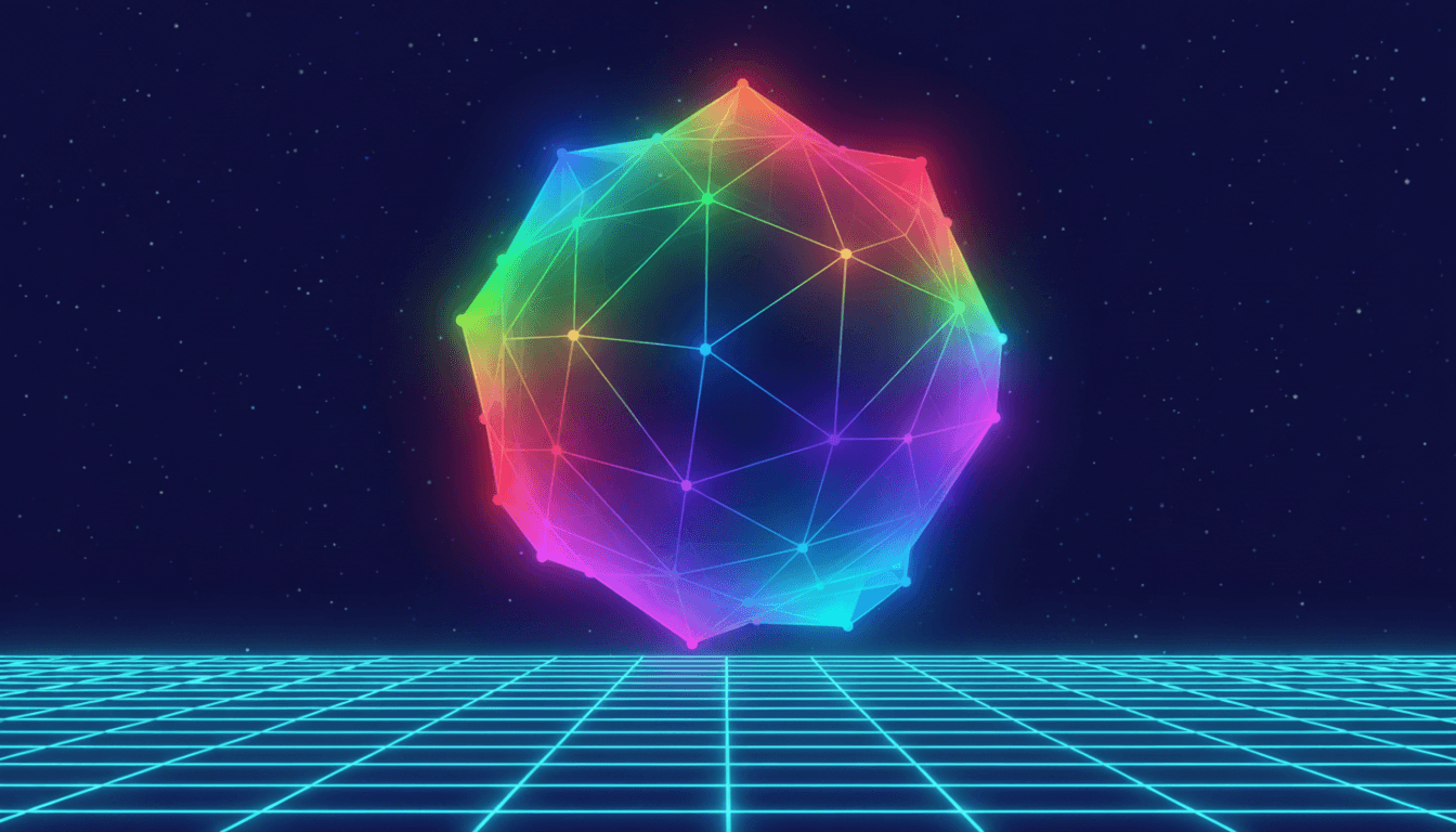
When you run the application, you will be greeted by a colorful, animating torus. You can use the keyboard to manipulate the material's properties in real-time and see how the shader responds.
Controls
| Key(s) | Action |
| 1, 2, 3, 4 | Switch between Vertex Color, UV, Position, and Normal visualization modes. |
| Spacebar | Toggle the wireframe overlay on and off. |
| \= / - | Increase / Decrease the speed of the vertex animation. |
What You're Seeing


This table explains what each visualization mode is showing you. Experiment with each one to build an intuition for how this data is stored and interpolated.
| Key | Mode | What It Demonstrates |
| 1 | Vertex Colors | This is the "raw" color data we baked into the mesh. A smooth rainbow gradient is created by assigning a different color to each vertex along the torus's main ring. |
| 2 | UV-Based Rainbow | This mode ignores the vertex colors and generates a new rainbow based on the u (horizontal) texture coordinate. This shows how UVs map around the mesh geometry. |
| 3 | Position-Based Gradient | Here, the color is determined by the vertex's height (its y position in local space). This is a common technique for effects like water depth or snow accumulation. |
| 4 | Normal Visualization | This classic debugging tool maps the X, Y, and Z components of the world normal vector to the R, G, and B color channels. It's a direct visualization of the surface orientation. |
Key Takeaways
You have now covered one of the most essential concepts in shader programming. The bridge between your mesh data and the GPU is no longer a mystery. Before moving on, ensure you have a solid grasp of these key points:
Standard Attributes: Meshes come with standard data channels like
POSITION(required),NORMAL,UV_0, andCOLOR. Each serves a distinct purpose, from defining shape to enabling lighting and texturing.Location Mapping: The
@location(N)decorator in your WGSL VertexInput struct is the crucial link to the mesh data on the CPU. The locations must match Bevy's standard layout, or the custom layout you define.Normals for Lighting: Normals are vectors describing surface orientation. They must be transformed using a special normal matrix (handled by Bevy's helper functions) and be re-normalized in the fragment shader for accurate lighting.
UVs for Surface Mapping: UVs are 2D coordinates that map a flat image or procedural pattern onto a 3D surface. They are typically passed directly from the vertex to the fragment shader.
Vertex Colors for Efficiency: Per-vertex colors allow for texture-free color gradients and are highly performant. They are interpolated smoothly across triangles.
Interpolation is Automatic: The GPU automatically blends all vertex shader outputs (except position) for each pixel of a triangle, creating smooth surfaces.
@interpolatefor Control: You can override the defaultperspectiveinterpolation withflatfor faceted shading or discrete data, andlinearfor screen-space effects.Custom Attributes are Powerful: You can create your own vertex attributes in Rust using
MeshVertexAttributeandinsert_attribute, then read them in your shader after configuring the pipeline with the specialize method.Data Flow: The vertex shader reads attributes, performs calculations, and passes its outputs to the fragment shader, which receives them as smoothly interpolated inputs.
What's Next?
You now have a complete understanding of how data gets from a mesh into your shaders and flows through the pipeline. We've read positions, normals, UVs, and colors, but so far, we've only transformed the object as a whole.
In the next article, we will take the next logical step: manipulating the vertex POSITION attribute itself. We'll move beyond simple MVP transformations and learn how to create dynamic, per-vertex effects like sine wave deformations, pulsing animations, and other simple procedural movements, all performed directly on the GPU.
Next up: 2.4 - Simple Vertex Deformations
Quick Reference
Standard Attributes & Shader Locations
| Bevy Attribute | WGSL Type | Shader Location |
Mesh::ATTRIBUTE_POSITION | vec3<f32> | @location(0) |
Mesh::ATTRIBUTE_NORMAL | vec3<f32> | @location(1) |
Mesh::ATTRIBUTE_UV_0 | vec2<f32> | @location(2) |
Mesh::ATTRIBUTE_COLOR | vec4<f32> | @location(3) |
Mesh::ATTRIBUTE_UV_1 | vec2<f32> | @location(4)* |
Mesh::ATTRIBUTE_TANGENT | vec4<f32> | Handled by PBR |
\Location assumes* COLOR is also present. Custom attribute locations must not conflict.
Interpolation Modes
| WGSL Attribute | Behavior | Use Case |
@interpolate(perspective) | Default. 3D perspective-correct. | Normals, UVs, Colors, World Positions. |
@interpolate(flat) | No interpolation. Constant across triangle. | Flat shading, integer IDs, discrete data. |
@interpolate(linear) | Screen-space linear blend. | 2D UI effects, post-processing. |
Custom Attributes in Rust
Define:
pub const MY_ATTR: MeshVertexAttribute = MeshVertexAttribute::new("Name", UNIQUE_ID, VertexFormat::Float32x2);Insert:
mesh.insert_attribute(MY_ATTR, vec![[0.0, 0.0], ...]);Specialize: In
impl Material, useget_layoutto mapMY_ATTR.at_shader_location(N)and update theRenderPipelineDescriptor.
Normal Transformation in WGSL
// Always use Bevy's helper to correctly handle non-uniform scaling.
let world_normal = mesh_functions::mesh_normal_local_to_world(
    in.normal,
    in.instance_index
);